Pillow plates
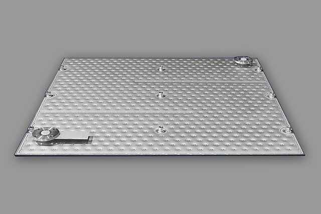
Pillow Plate Heat Exchangers (PPHE) are a special heat exchanger design in which two sheets of metal are welded together by laser welding or resistance welding to form a closed pressure chamber. A laser-welded or resistance-welded spot pattern is defined within the pressure space in order to achieve the pressure resistance required by the customer and also to generate maximum fluid mechanical and thermodynamic efficiency. The spot pattern is the characteristic element of laser pillow plate heat exchangers and has been defined to perfection by the engineers at BUCO for many decades, either for cooling or heating process purposes.
Pillow plates have become an increasingly popular heat exchanger due to their advantages over conventional heat exchangers. Despite this, knowledge of pillow plate thermohydraulic performance and experience with pillow plate design is limited. As such, the development of commercial software tools has become necessary in order to bridge this gap. A rough breakdown of current pillow plate research can be found in the referenced material, which is divided into three distinct areas: geometrical analysis, fluid flow and heat transfer analysis within pillow plates and fluid flow and heat transfer between adjacent pillow plates. Such efforts are undoubtedly needed to develop pillow plate technology and optimize their effectiveness as efficient heat exchangers.

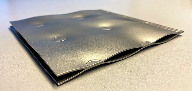
After the pillow plate heat exchanger is completely welded, the volume of the pressure chamber is defined by pneumatic cold deformation of the inner space under high pressure. This parameter complements the variables mentioned above and is determined by engineers at BUCO. The so-called press-on height, maximum clear distance between both inner surface sides of the plate, defines the flow cross-sections in the pre-welded spot pattern and forms the characteristic visual surface design of a pillow plate heat exchanger. In addition, strain hardening during the pneumatic deformation process creates the stability of the mostly stainless steel laser pillow-plates.
Pillow plates have numerous thermohydraulic calculations associated with them - such as surface area, fluid hold-up volume, cross-sectional area and hydraulic diameter. These parameters are crucial in determining the burst pressure of pillow plates. Methods for evaluating these parameters have been proposed in various research studies using Finite Element Analysis (FEM). This analysis accurately imitates the inflation process of pillowplates during manufacturing, providing us with a reliable estimation of pillowplate burst pressures. Thus, FEM continues to be a popular method used in determining pillow plate parameters and can allow for accurate predictions concerning pillow plate structure properties.

Looking for "Pillow Type Plate Heat Exchanger"? How to select a Pillow Plate?
According to the customer's requirements, cooling or heating processes, we define the welding spot pattern on our laser machines and the internal channel height as a result of different variables of the Pillow Type Plate Heat Exchanger, such as:
- Sheet metal material of pillow-plates (e.g. DC01, DC04, 304, 304L, 316L, 316Ti, 318LN, 904L, 254 SMO, etc.)
- Sheet wall thicknesses of pillow-plates (e.g. 0.6 mm, 0.8 mm, 1.0 mm, 1.5 mm, 2.0 mm, 3.0 mm, etc.)
- Maximum allowable pillow plate pressure
- Maximum allowable pillow plate temperature
- Fluid inside the pillow plate heat exchanger
- Fluid outside the pillow plate heat exchanger
- Flow rate through the pillow plate heat exchanger
- Maximum allowable pressure drop of the pillow plate heat exchanger
Our decades of expertise in interacting with the above variables can be applied to all conceivable fluids in the heat exchange plate. These include:
- Single-phase fluids in process applications of pillow-plates such as water, thermal oils, or highly viscous fluids such as flycol-water mixtures
- Single-phase superheated gases in process applications of pillow-plates
- Fluids that evaporate in the pillow plate (e.g. natural refrigerants, freons)
- Fluids that condense in the pillow plate (e.g. steam)
Maximum allowable pressures PS >70bar or maximum allowable temperatures TS > 400°C can be achieved thanks to BUCO's outstanding know-how.
Our advantages of pillow plate heat exchanger?
The versatility of pillow plate heat exchangers leads to an almost unlimited range of applications, especially where complex pillow plate geometries are required due to complicated base bodies and mounting options.
Allowable pillow plate pressure and pillow plate burst pressure test
The allowable pressure inside the pillow plates is verified by burst pressure tests. These burst pressure tests are usually carried out on samples of the pillow plate with the same strength-determining properties as the pressure vessels to be manufactured (material, sheet thickness, weld spot pattern, etc.). To determine the burst pressure PB, the pressure in the test specimen is gradually increased in the presence of an expert from the responsible testing organization until it bursts. This procedure thus belongs to the destructive tests. The weld spot pattern of the pillow plate which is required achieve the required burst pressure is determined by the engineers at BUCO. Burst pressures > 450 bar are readily achievable. The calculation of the maximum allowable pressure PS from the achieved burst pressure PB is done e.g. according to AD 2000 Merkblatt S5 or the ASME code. In very simplified terms, the burst pressure must be more than five times the maximum allowable pressure.
Flow and heat transfer of pillow plate heat exchangers
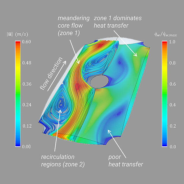
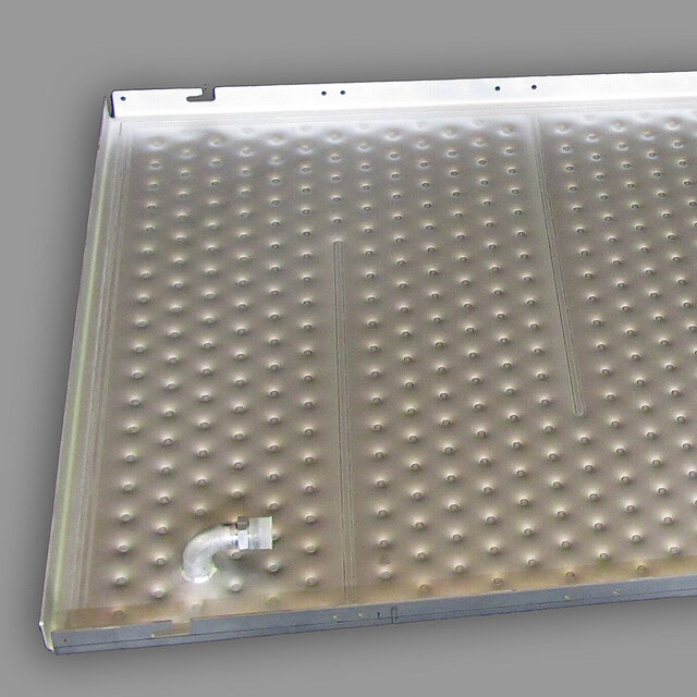
To ensure that the pillow plate heat exchanger works as efficiently as possible for all fluid groups, optimum flow arrangement used within the pressure chamber is a top priority in the selection process. To achieve this, among other things, seam welds are placed in the welding spot pattern to guide the fluid through the pillow plate. An optimum combination of welding spot pattern and channel height support the best possible flow distribution by specifically influencing the flow cross-sections. This minimizes dead spaces and poorly flowed areas used in the pillow plate. This has been confirmed for decades by verifications on test rigs and customer installations, making BUCO's customized pillow plate geometries the most efficient on the market.
Due to the flow within the three-dimensional pillow profile with regularly repeating changes in cross-section and direction, turbulent flows can be generated even at low Reynolds numbers, resulting in comparatively high internal heat transfer coefficients at an early stage. As a result, under the same conditions outside the heat exchange plate, the overall heat transfer coefficient increases and the required heat exchange area decreases. This advantage is particularly evident in comparison with tube flow in tube bundles, which are significantly more inefficient for geometric reasons. As a result, BUCO's pillow plate heat exchangers are also more resource-efficient and sustainable, as the amount of steel required is significantly lower than for solutions with tubes. In addition, solutions with tubes, coils or tube bundles are extremely inflexible in design, making them inferior to pillow plates in many applications. The above advantages can be applied to all the fluid groups mentioned above, which BUCO has mastered to perfection for many decades.
Pillow plate heat exchanger applications?
Where are pillow-plates mostly used for ?
Double embossed pillow plate plates are mostly installed for the heat exchange in sterilization ovens, drying cabinets in the pharmaceutical industry and industrial drying ovens. It guarantees absolutely even heat mass flow and low pressure drop due to large flow cross sections of the pillow plate. A complete cylinder tank is made from laser welded single embossed panels, of those, the profiles have not been blown up then. The flow profile of the heat exchange panel will be blown up after the tank has been build. The dimple plate surface inside the tank is not damaged by the laser welding process. To re-polish the inside surface is no longer required.
Allowable pressure and burst pressure test
The allowable pressure inside the pillow plates is verified by burst pressure tests. These burst pressure tests are usually carried out on samples of the pillow plate with the same strength-determining properties as the pressure vessels to be manufactured (material, sheet thickness, weld spot pattern, etc.). To determine the burst pressure PB, the pressure in the test specimen is gradually increased in the presence of an expert from the responsible testing organization until it bursts. This procedure thus belongs to the destructive tests. The weld spot pattern of the pillow plate which is required achieve the required burst pressure is determined by the engineers at BUCO. Burst pressures > 450 bar are readily achievable. The calculation of the maximum allowable pressure PS from the achieved burst pressure PB is done e.g. according to AD 2000 Merkblatt S5 or the ASME code. In very simplified terms, the burst pressure must be more than five times the maximum allowable pressure.
Flow and heat transfer
To ensure that the pillow plate heat exchanger works as efficiently as possible for all fluid groups, optimum flow arrangement within the pressure chamber is a top priority. To achieve this, among other things, seam welds are placed in the welding spot pattern to guide the fluid through the pillow plate. An optimum combination of welding spot pattern and channel height support the best possible flow distribution by specifically influencing the flow cross-sections. This minimizes dead spaces and poorly flowed areas in the pillow plate. This has been confirmed for decades by verifications on test rigs and customer installations, making BUCO's customized pillow plate geometries the most efficient on the market.
Due to the flow within the three-dimensional pillow profile with regularly repeating changes in cross-section and direction, turbulent flows can be generated even at low Reynolds numbers, resulting in comparatively high internal heat transfer coefficients at an early stage. As a result, under the same conditions outside the heat exchange plate, the overall heat transfer coefficient increases and the required heat exchange area decreases. This advantage is particularly evident in comparison with tube flow in tube bundles, which are significantly more inefficient for geometric reasons. As a result, BUCO's pillow plate heat exchangers are also more resource-efficient and sustainable, as the amount of steel required is significantly lower than for solutions with tubes. In addition, solutions with tubes, coils or tube bundles are extremely inflexible in design, making them inferior to pillow plates in many applications. The above advantages can be applied to all the fluid groups mentioned above, which BUCO has mastered to perfection for many decades.

